Mode/AP Selection blocks
Mode/AP Selection blocks allow to interact with flight modes and redundancy (Autopilot 4x).
AP Selection
AP selection block is a Veronte Autopilot 4x consensus. This block behaves differently depending on the selected AP:
If this AP is the selected one then the input is copied into the output and the input is sent to the other APs via CAN (needed to have correct CAN ports configuration).
If this AP is not the selected one then the outputs are the received values via CAN from the selected AP.
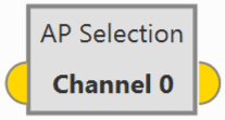
AP Selection block
Input
 Pin 0: Values computed by this AP.
Output
Pin 0: Values computed by the selected AP.Configuration menu: The user must select the channel through which information is shared between the APs.
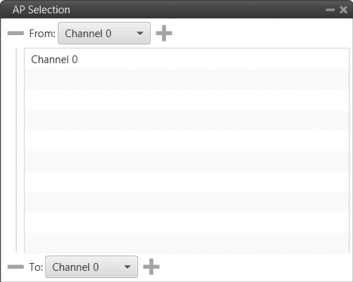
AP Selection block configuration
This block normally is used for the control outputs. The APs share the control outputs with each other so that they all use the control output of the selected AP. Therefore, the input is the control output of the AP in the configuration and the output is the control output of the selected AP. This can actually be used with any type of variable that you want to share and use the selected AP’s variable.
This block is intended to be used as input for the inner loop PID (at control rate), so that the Integral term of the 3 Autopilots 1x of the Autopilot 4x remains the same. This way, if the selected autopilot from the 4x is switched to one of the other 2 available autopilots, a smooth response without significant ‘jumps’ in control will still be obtained. An example of this use is shown below:
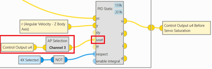
AP Selection block - Example of use
Arcade
Arcade Pure block switches between two input signals according to the current mode of the configured channel. Refer to the modes configuration table to check the configuration (go to Modes panel in the Control menu).
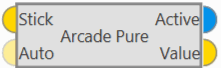
Arcade block
Inputs
Stick: Arcade value to be applied when the configured channel is in arcade mode. (Optional) Auto: Auto value to be applied when the configured channel is not in arcade mode. The default value if not connected is zero.
Outputs
 Active: TRUE if the configured channel is in arcade mode, FALSE otherwise. Value: Value to apply. In arcade mode, this value is equal to the first input (arcade value) and in any other mode is equal to the second input (auto value).
Configuration menu:

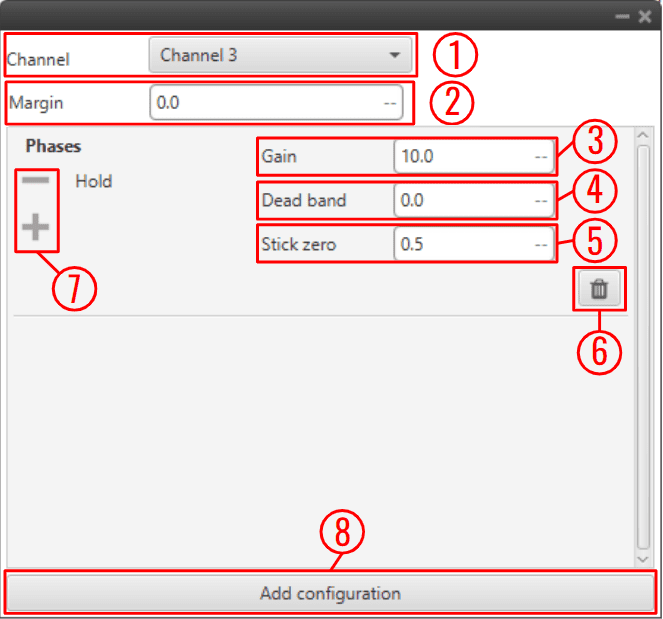
Arcade block configuration
The following parameters must be configured:
Channel: Channel controlled by this block. Be careful, each channel is related to a control output previously defined in the Modes panel of the Control menu.
Zero enabled: It can be enabled by the user.
Disabled: If the stick is in position “0”, even if it is in arcade mode, the autopilot processes it as if it were in auto mode, and consequently, the value of the output active will be false and the value of the output value will be that of the auto input.
Enabled: If the stick is in position “0” and in arcade mode, the autopilot still processes it as being in arcade mode, so the output active value will be true and the output value will be that of the stick input.
Gain: The output value is the result of multiply the stick input by this gain.
Dead band: Creates a zone where the movement of the stick is not sent to the system.
Stick zero: Output value when the value of the stick input is 0.
Note
The following diagram details the differences between the parameters Dead band and Stick zero:

Arcade block configuration - Dead band VS Stick zero
Delete a group of phases.
Delete/Add a phase to a group.
Add configuration: Add a new group of phases affected by this block.
Arcade Bounce
Arcade Bounce block switches between two input signals according to the current mode of the configured channel preventing bounces in transitions from arcade to auto. Refer to the mode configuration table to check the configuration (go to Modes panel in the Control menu).

Arcade Bounce block
In the pictures below there is an example controlling the yaw.
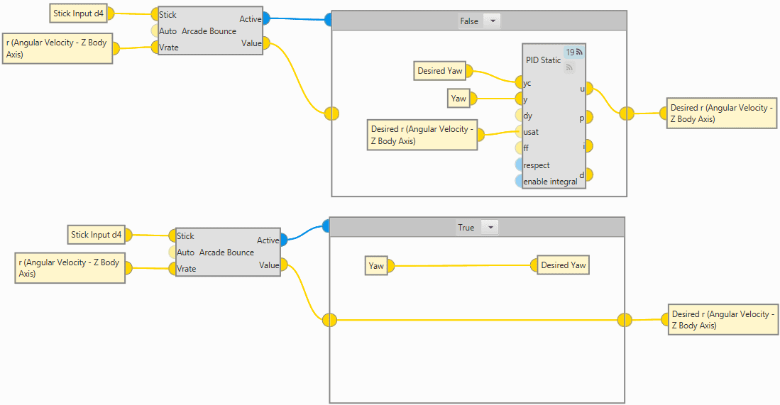
Arcade Bounce block example
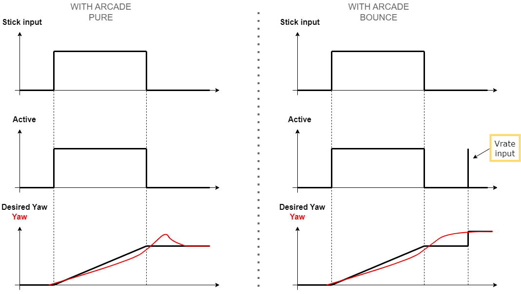
Arcade Pure VS Arcade Bounce
This example is explained below:
When the stick is in its zero position, the command sent is 0, so the status of the Active BIT is FALSE (low level), and the desired yaw is the last yaw saved when the status was TRUE (high level).
However, the platform can still have a yaw rate (r (Angular Velocity) variable in the block example) and in an arcade pure block it could experiment this bounce.
Therefore, with the Arcade Bounce block, when the Yaw rate (Vrate input) approaches 0 (changes its sign), this BIT reverts to TRUE (for a moment), and even though a new yaw rate is not being commanded with the stick, the desired yaw is being updated with the current yaw.
As it is very similar to the Arcade Pure block, the inputs and outputs are the same, except that an additional input is added to this block:
Input
Vrate: Controlled variable used to prevent bounces.Configuration menu:
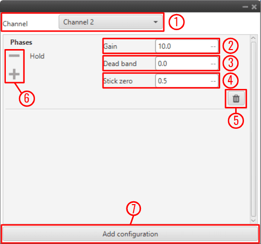
Arcade Bounce block configuration
The following parameters must be configured:
Channel: Channel controlled by this block. Be careful, each channel is related to a control output previously defined in the Modes panel of the Control menu.
Gain: The output value is the result of multiply the stick input by this gain.
Dead band: Creates a zone where the movement of the stick is not sent to the system.
Stick zero: Output value when the value of the stick input is 0.
Delete a group of phases.
Delete/Add a phase to a group.
Add configuration: Add a new group of phases affected by this block.
Arcade Extend
Arcade Extend block switches between two input signals according to the current mode of the configured channel smoothing the transition by extending the arcade mode until the input ‘Val’ goes below the configured margin. (Similar to Arcade Bounce block). Refer to the mode configuration table to check the configuration (go to Modes panel in the Control menu).
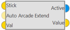
Arcade Extend block
As it is very similar to the Arcade Pure block, the inputs and outputs are the same, except that an additional input is added to this block:
Input
Val: Controlled variable used to extend the arcade to auto transitions.Configuration menu:
Arcade Extend block configuration
The following parameters must be configured:
Channel: Channel controlled by this block. Be careful, each channel is related to a control output previously defined in the Modes panel of the Control menu.
Margin: If the ‘Val input’ is higher than the margin set here, the autopilot will remain in arcade mode.
Gain: The output value is the result of multiply the stick input by this gain.
Dead band: Creates a zone where the movement of the stick is not sent to the system.
Stick zero: Output value when the value of the stick input is 0.
Delete a group of phases.
Delete/Add a phase to a group.
Add configuration: Add a new group of phases affected by this block.
Manual
Manual block switches between two input signals according to the current mode of the configured channel. Refer to the mode configuration table to check the configuration (go to Modes panel in the Control menu).
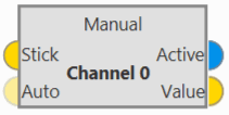
Manual block
Inputs
Stick: Manual value to be applied when the configured channel is in manual mode. (Optional) Auto: Manual value to be applied when the configured channel is not in manual mode. The default value if not connected is zero.Outputs
Active: TRUE if the configured channel is in manual mode, FALSE otherwise. Value: Value to apply, which in manual mode is equal to the first input (manual value) and in any other mode is equal to the second input (auto value).Configuration menu: The user must select the channel to be controlled.
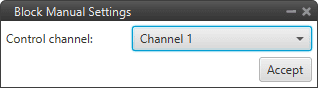
Manual block configuration
Mix
Mix block adds a ‘Stick’ signal to an ‘Auto’ signal if the current mode for the configured channel is MIX, otherwise the output is directly the ‘Auto’ signal. In other words, it allows a variable offset to be applied to the input using one of the stick channels.
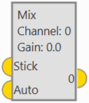
Mix block
Inputs
Stick: Value to be added to ‘Auto’ when the configured channel is in MIX mode. Auto: Auto value.Output
0: If the configured mode of the configured channel is MIX the output is the addition of ‘Stick’ and ‘Auto’, otherwise the output is directly ‘Auto’.Configuration menu:
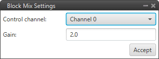
Mix block configuration
The following parameters can be configured:
Channel: The user must select the channel to be controlled.
Gain: This gain will multiply the ‘Stick’ input (before the addition with the ‘Auto’ input) if the current mode is MIX.